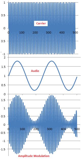
The algorithm for generating the Amplitude Modulation (AM)
The algorithm
|
|
|
|
|
|
|
|
|
Step 1
|
|
|
The mathematical formulation of the data
|
|
+ |
|
= |
|
= |
|
+ |
|
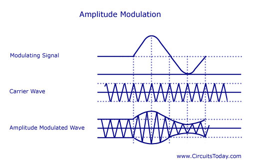
Modulation
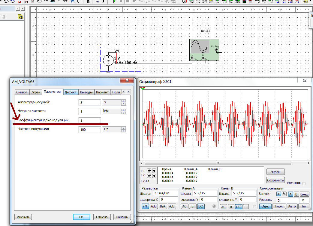
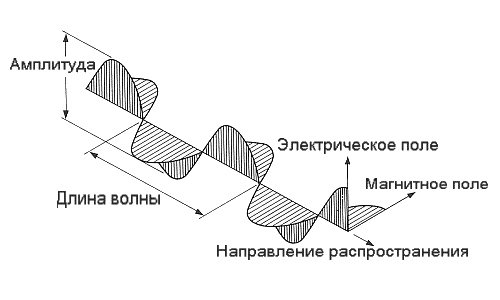
Amplitude Modulation-является наиболее простым и распространенным способом изменения параметров носителя информации.
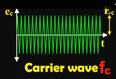
При AM амплитуда E(t) гармонического колебания
|
|
|
|
|
 |
|
|
|
|
|
|
|
|
|

|
|
12.6 |


|
|
|
|
|
|
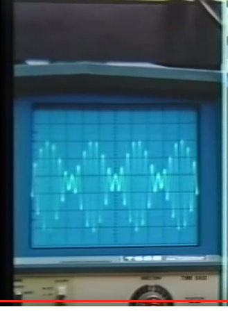
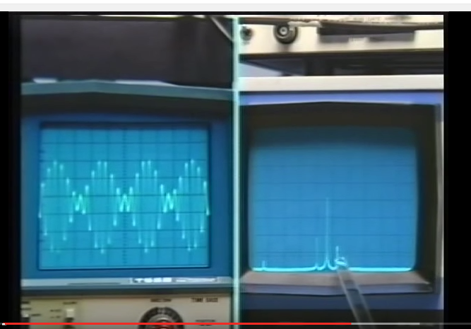
Over Modulation
If the modulation depth rises above 100%, the transmission looks like this.
|
|
|
|
|
|
|
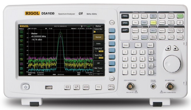
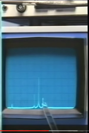
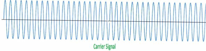
Спектры рис.12.9 получены на анализаторе спектров A = x(f)
Spectrum Analyzer
|
|
|
|
|
|
|
|
|
|
|
|
|
|
|
|
|
|
|
|
|
|
(несущего сигнала) изменяется по закону изменения передаваемого информационного сигнала.
В радиотехнике AM применяют для передачи информации на расстояние в радиовещании,акустической локации и др.
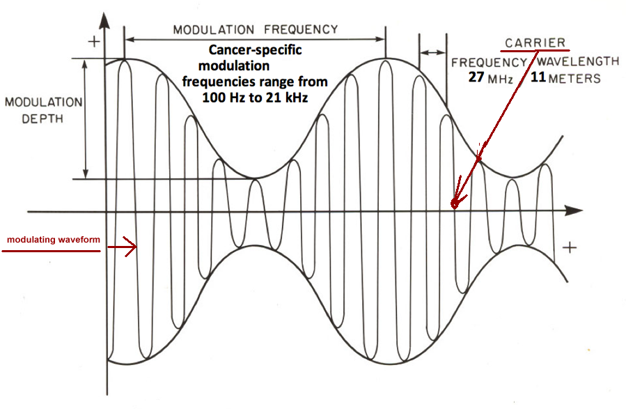
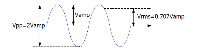
Основной характеристикой амплитудной модуляции является modulation depth (коэффициент амплитудной модуляции или глубина модуляции –
отношение разности между максимальным и минимальным значениями амплитуд модулированного сигнала к сумме этих значений, выраженное в процентах.
|
 |
Step 2
|
|
|
Verification of theoretical data
Step 3
|
|
|
Verification of experimental data
Amplitude Modulation (AM)
Analog-to-Analog Conversion
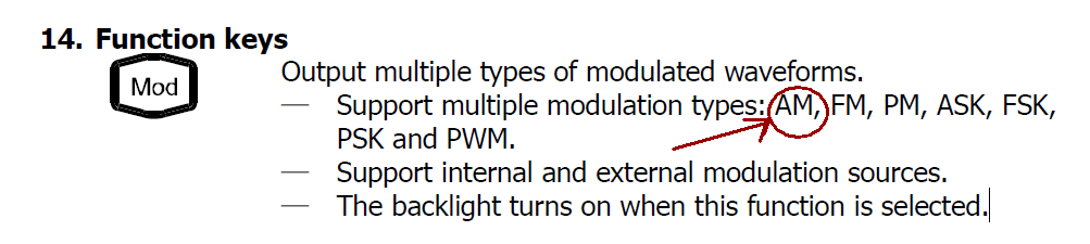
DG1000Z can output modulated waveform from a single channel or from two channels at the same time.
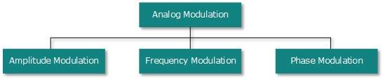
Modulation is the process of modifying certain(некоторые) parameters (such as amplitude, frequency,
phase and etc.) of the carrier waveform signal according(зависимости от) to the change of the modulating signal.
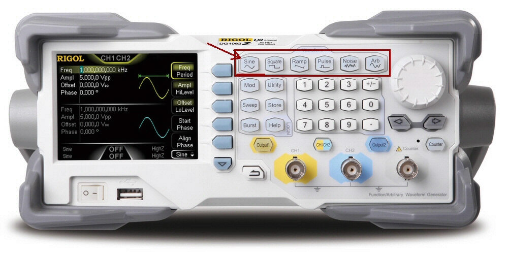
The carrier(несущей) waveform can be Sine, Square, Ramp, Arbitrary waveform (except(кроме) DC) or Pulse (only in PWM).
The modulating waveform can be from internal or external modulation source. DG1000Z supports AM, FM, PM, ASK, FSK, PSK and PWM.
Amplitude Modulation (AM)
For amplitude modulation (AM), the amplitude of the carrier waveform varies(меняется) with the instantaneous(мгновенная) voltage of the modulating waveform.
Multiple analog and digital modulations
To Output AM Modulated Waveform
For amplitude modulation (AM), the amplitude of the carrier waveform varies with the instantaneous voltage of the modulating waveform.
This section introduces how to output AM modulated waveform from the [CH1] connector
(the
|
carrier(Огибающия кривая = несущия сигнала ) = sine
modulating waveform(модулирующий сигнал) = sine modulation depth = 80%.
|
modulation depth is 80%). |
To Select AM Modulation
1.Step
To select output channel
Press CH1|CH2 to select CH1. Now the boarder of the channel status bar is displayed in yellow.
2.Step
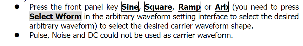
To Select Carrier Waveform Shape(форма= график функции= несущия сигнала )
2.1 .Step
Carrier Waveform Shape: press Sine to select sine as the carrier waveform.
AM carrier waveform could(может) be Sine, Square, Ramp or Arbitrary waveform (except DC).
3.Step To Set Carrier Waveform ParametersВЫ
For all carrier waveform shapes, the default
values
are 1kHz frequency,
5Vpp amplitude,
0VDC offset
and 0° start phase.
|
|
The different(различные) settings of various parameters (frequency, amplitude, DC offset, start phase and etc.)
of the carrier waveform will influence(влияет) the AM modulated waveform.

For different carrier waveform shape, the ranges of the various parameters are different

(the ranges are related to the model of the instrument used and the carrier waveform currently selected.
See “Specifications” for details).


3.0 To set the carrier waveform shape, frequency and amplitude
3.1 frequency=5kHz
Carrier Frequency: press Freq/Period to highlight “Freq”.
At this point, use the numeric keyboard to input 5.
Then, select kHz from the pop-up menu.
3.2 amplitude =5Vpp
Carrier Amplitude: press Ampl/HiLevel to highlight “Ampl”, and then use the numeric keyboard to input 5. Then, select Vpp from the pop-up menu.
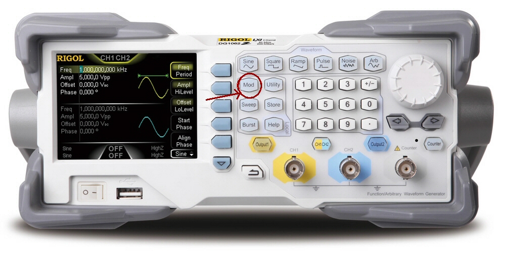
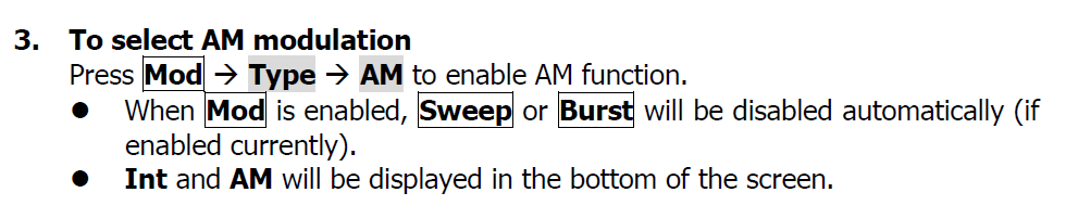
4. To select AM modulation
C:\5\Осцилограф\генератор\меню
DG1000Z_QuickGuide_CN&EN
4.Step
To set Modulating waveform frequency
frequency = 200Hz
Press AM Freq, and then use the numeric keyboard to input 200. Then, select Hz from the pop-up menu.
5.Step
To select modulating waveform
Press Shape to select Sine from the pop-up menu.
|
The default is Sine. |
|
6.Step
To set modulation depth(%)
modulation depth = 80%.
Press AM Depth, and then use the numeric keyboard to input 80. Then, select % from the pop-up menu.
7.Step
To enable the output
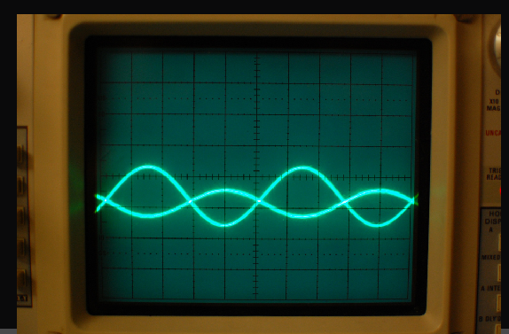
Press Output1 to turn CH1 output on. At this point, the backlight(подсветка) goes on and the [CH1] connector outputs the AM modulated waveform based on the current settings.
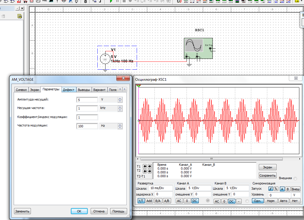
8.Step
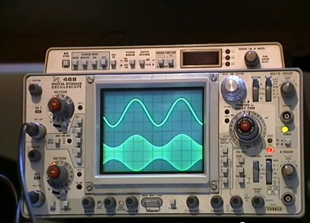
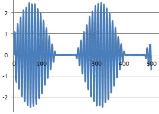
To observe the output waveform
Connect the [CH1] connector to the oscilloscope using BNC cable. The waveform is as shown in the figure below.
|
|
|
The different settings of various parameters (frequency, amplitude, DC offset, start phase and etc.) of the carrier waveform will influence the AM modulated waveform.
For different carrier waveform shape, the ranges of the various parameters are different
(the ranges are related to the model of the instrument used and the carrier waveform currently selected.
See “Specifications” for details).
To Select Modulation Source
The default is Sine.

1. Internal Source
When internal modulation source is selected, press Shape to select Sine, Square, Triangle, UpRamp, DnRamp, Noise or Arb as modulating waveform.
Square: 50% duty cycle
Triangle: 50% symmetry
UpRamp: 100% symmetry
DnRamp: 0% symmetry
Arb: the arbitrary waveform selected of the current channel
Note: noise can be used as modulating waveform but can not be used as carrier waveform.
()
2. External Source
When external modulation source is selected, Shape and AM Freq will be grayed out and disabled.
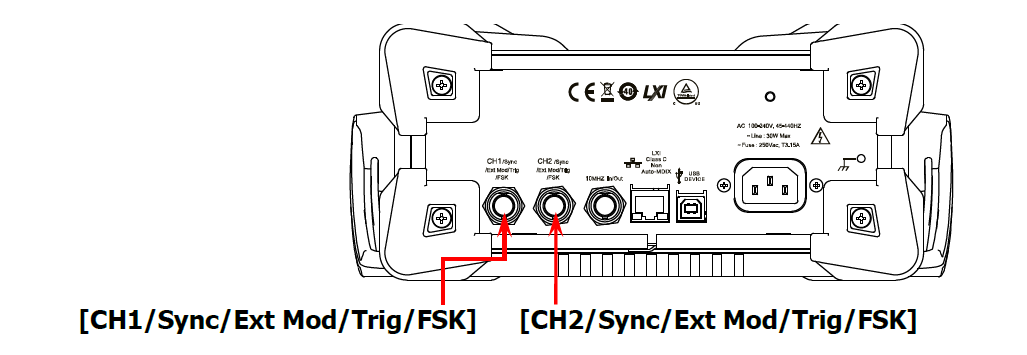
The generator accepts the external modulating signal from the [CH1/Sync/Ext Mod/Trig/FSK] connector at the rear panel.
At this time, amplitude of the modulated waveform is controlled by the ±5 V signal level of the connector.
For example, if the modulation depth is set to 100%, the output amplitude will be the maximum when the modulating signal is +5V and the minimum when the modulating signal is -5V.
|
|
|
KEY POINTS:
How to realize the intermodulation between dual channels? The following example takes the output signal of CH2 as the modulating waveform.
1. Connect the CH2 output terminal to [CH1/Sync/Ext Mod/Trig/FSK] connector at the rear panel using the dual BNC connect cable.
2. Select CH1 and press Mod to select the desired modulation type as well as set the corresponding parameters before selecting external modulation source.
3. Select CH2 and select the desired modulating waveform and set the corresponding parameters.
4. Press Output1 to enable the output of CH1.
5.Step

To Set Modulating Waveform Frequency
default value is 100Hz.
When internal modulation source is selected, press AM Freq to set the modulating waveform frequency.
Input the desired frequency value using the numeric keyboard or direction keys and knob。
The modulating waveform frequency ranges from 2mHz to 1MHz, and the default value is 100Hz.
Note: when external modulation source is selected, this menu will be grayed out and disabled.
6.Step

To Set Modulation Depth

 Modulation depth expressed as a percentage indicates the amplitude variation degree.
The AM modulation depth ranges from 0% to 120%.
Press AM Depth to set AM modulation depth.
In 0% modulation, the output amplitude is half of the carrier waveform amplitude.
In 100% modulation, the output amplitude is equal to carrier waveform amplitude.
In >100% modulation, the output amplitude of the instrument would not exceed 10Vpp (50Ω load).
When external modulation source is selected, the output amplitude of the instrument
is controlled by the ±5V signal level of the [CH1/Sync/Ext Mod/Trig/FSK] connector at the rear panel.

For example, if the modulation depth is set to 100%,
the output amplitude will be the maximum when the modulating signal is +5V and the minimum when the modulating signal is -5V.

Carrier Waveform Suppression(подавление)
 DG1000Z supports the normal amplitude modulation and double sideband suppressed carrier (DSB-SC) amplitude modulation.
In the normal amplitude modulation, the modulated waveform contains carrier waveform components.
Because carrier waveform components carry no information, the modulation is less efficient.
In order to improve the modulation efficiency, the carrier waveform components are suppressed on the base of the normal amplitude modulation.
At this time, all modulated waveform carry information. This method is called double sideband suppressed carrier modulation.
By default, DG1000Z works in the normal amplitude modulation and users can enable the double sideband suppressed carrier modulation
through pressing the menu key DSSC and selecting “On”.