To Output Basic Waveform
how to output a Sine waveform in DG1000Z
|
|
|
Алгоритм
|
|
|
|
|
|
|
|
|
how to output a sine waveform in DG1000Z
Step 1
|
|
|
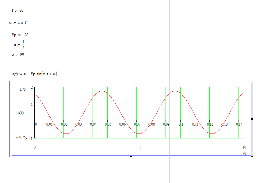
The mathematical formulation of the data
This section introduces how to output a sine waveform
from the [CH1] connector.
Frequency = 20kHz
Amplitude = 2.5Vpp
DC Offset = 500mVDC
Start Phase = 90°
Step 2
|
|
|
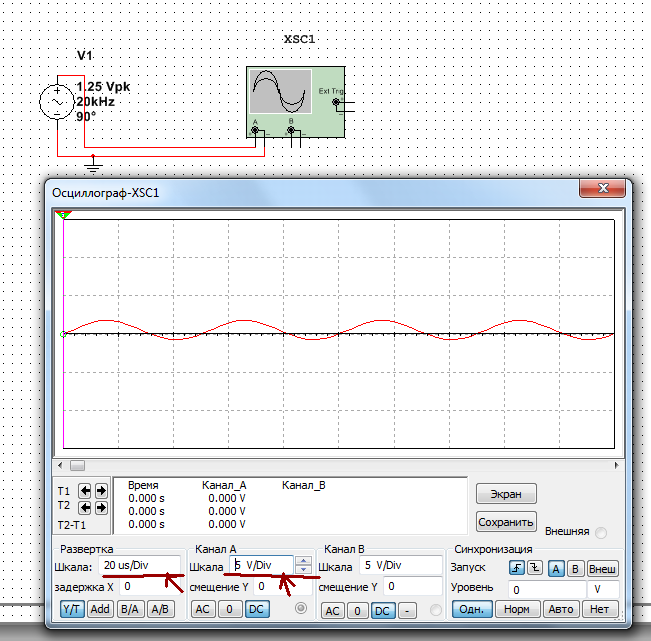
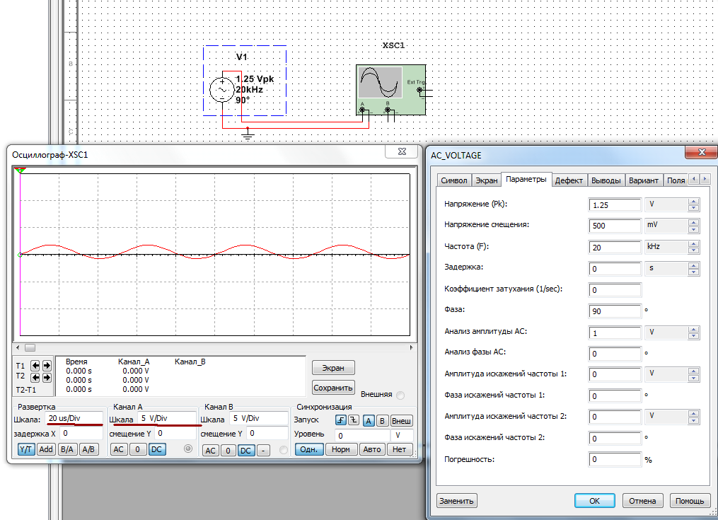
Verification of theoretical data
| Эксперементальные данные | Теоретические данные | Математические данные |
|
Frequency = 20kHz |
|
f := 20 |
|
Amplitude = 2.5Vpp |
Vp = 1.25 | |
|
DC Offset = 500mVDC |
|
|
|
Start Phase = 90° |
 |
|
|
|
Step 3.
|
|
|
Verification of experimental data
|
|
|
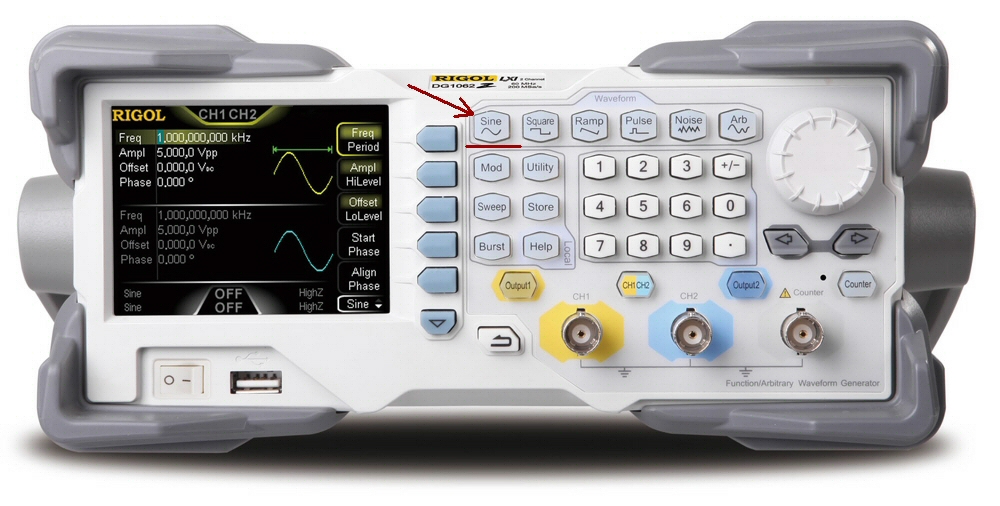
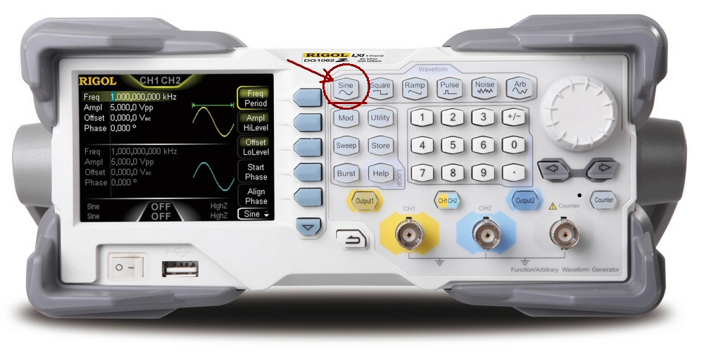
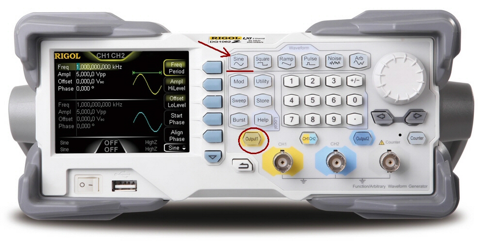
1. To select output channel
Press CH1|CH2 to select CH1. Now the boarder of the channel status bar is displayed in yellow.
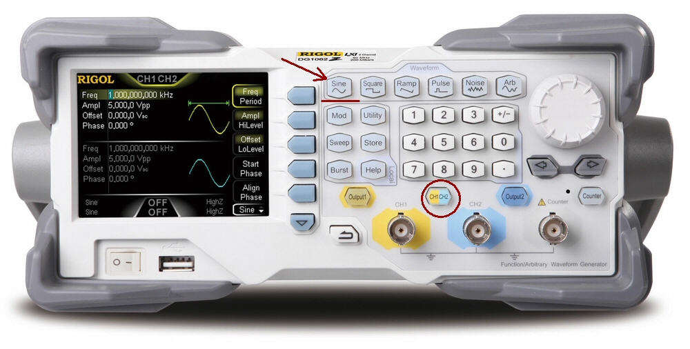
2. To select the Sine
Press Sine to select the sine waveform. The backlight goes on and the corresponding menu is displayed in the right of the screen.
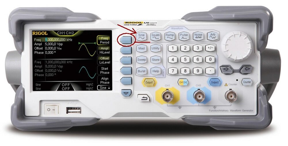
3. To set the frequency/period
Frequency = 20kHz
Press Freq/Period to highlight “Freq”, and then use the numeric keyboard to input 20. Then select kHz from the pop-up menu.
The frequency ranges from 1μHz to 60MHz.
The frequency units available are MHz, kHz, Hz, mHz and μHz.
Press this softkey again to switch to period setting.
The period units available are sec, msec, μsec and nsec.
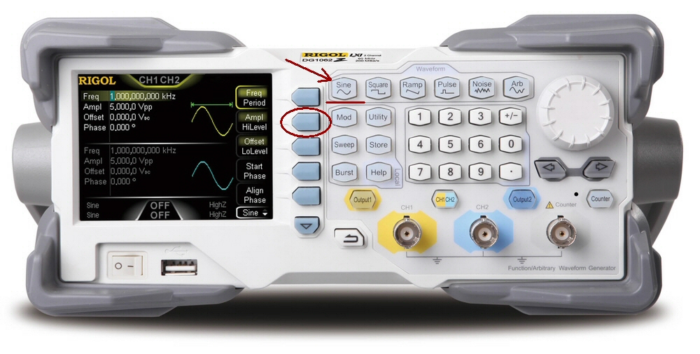
4. To set the amplitude
Amplitude = 2.5Vpp
Press Ampl/HiLevel to highlight “Ampl”, and use the numeric keyboard to input 2.5.
Then, select Vpp from the pop-up menu.
The amplitude range is limited by the impedance and frequency/period.
The amplitude units available are Vpp, mVpp, Vrms, mVrms and dBm (dBm is only valid when the setting in Utility Channel Set Output Set Imped is not HighZ).
Press this softkey again to switch to high level setting.
The high level units available are V and mV.
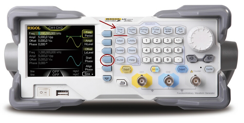
5. To set the offset
DC Offset = 500mVDC
Press Offset/LoLevel to highlight “Offset”, and then use the numeric keyboard to input 500. Then, select mVDC from the pop-up menu.
The range of the offset is limited by the impedance and frequency/period.
The DC offset voltage units available are VDC and mVDC.
Press this softkey again to switch to low level setting. The low level must be lower than the high level at least 1mV (when the output impedance is 50Ω).
The low level units available are V and mV.

6. To set the start phase
Start Phase = 90°
Press Start Phase, and then use the numeric keyboard to input 90. Then, select ° from the pop-up menu.
The start phase ranges from 0° to 360°.
7. To enable the output
Press Output1 to turn CH1 output on. At this point, the backlight goes on and the [CH1] connector outputs waveform with the specified parameters.
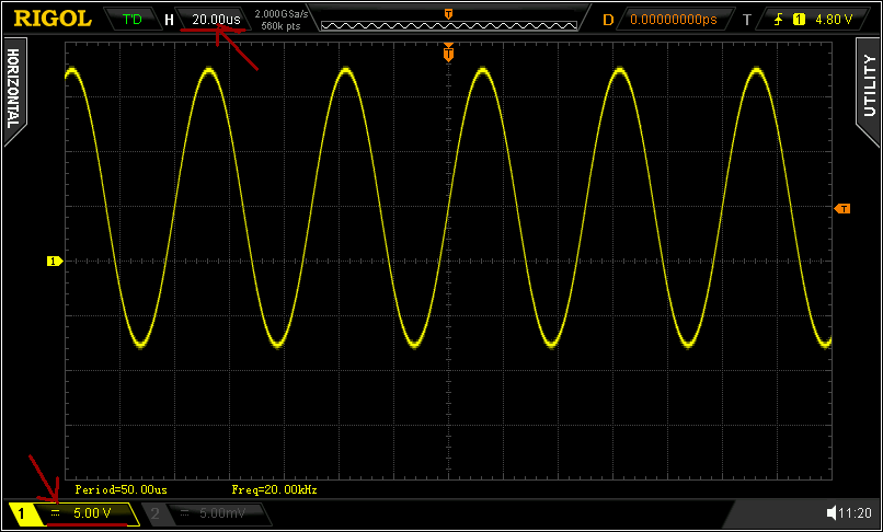
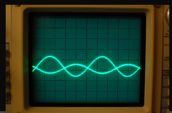
8. To observe the output waveform
Connect the [CH1] connector to the oscilloscope using BNC cable. The waveform is as shown in the figure below.
Step 9
Measure(Измеряем) and compare(сравниваем) with theoretical data.
|
experimental data |
theoretical data |
|
|
|


.jpg)